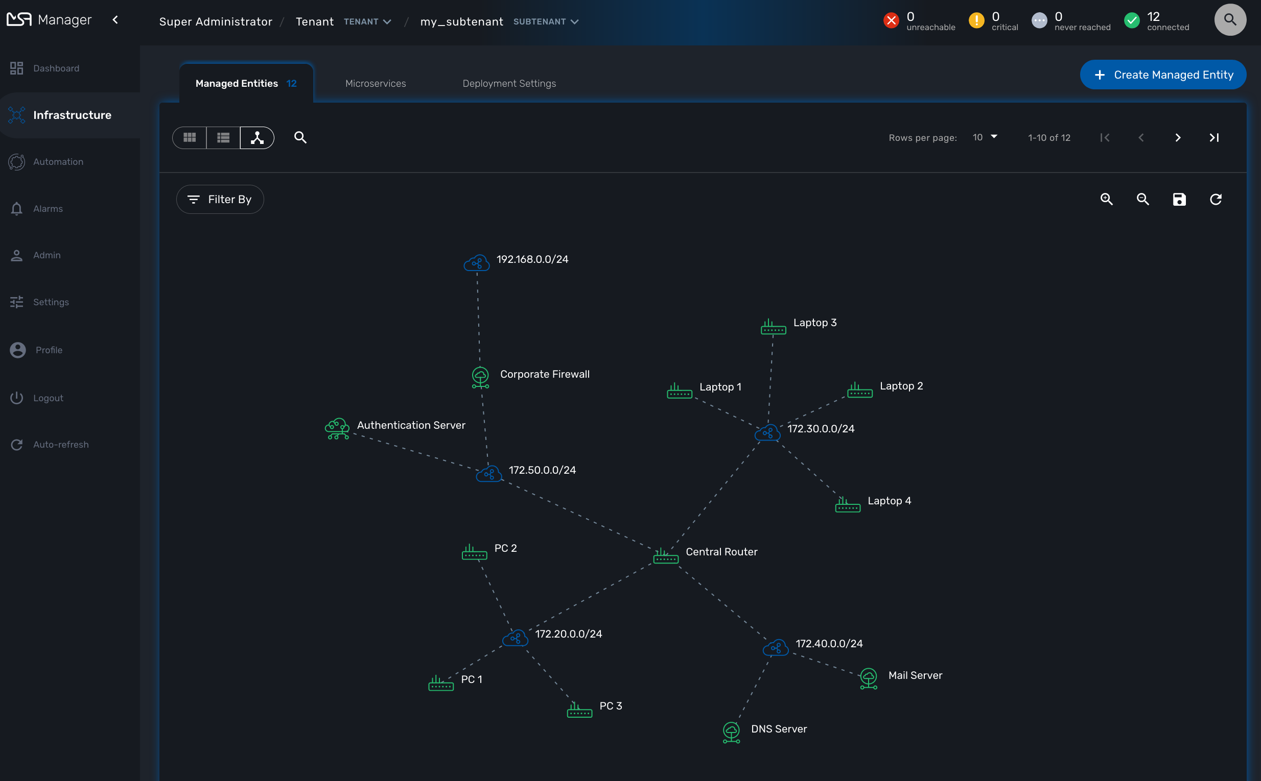
The topology view is available on the portal and provides a graphical view of your network.
Topology view
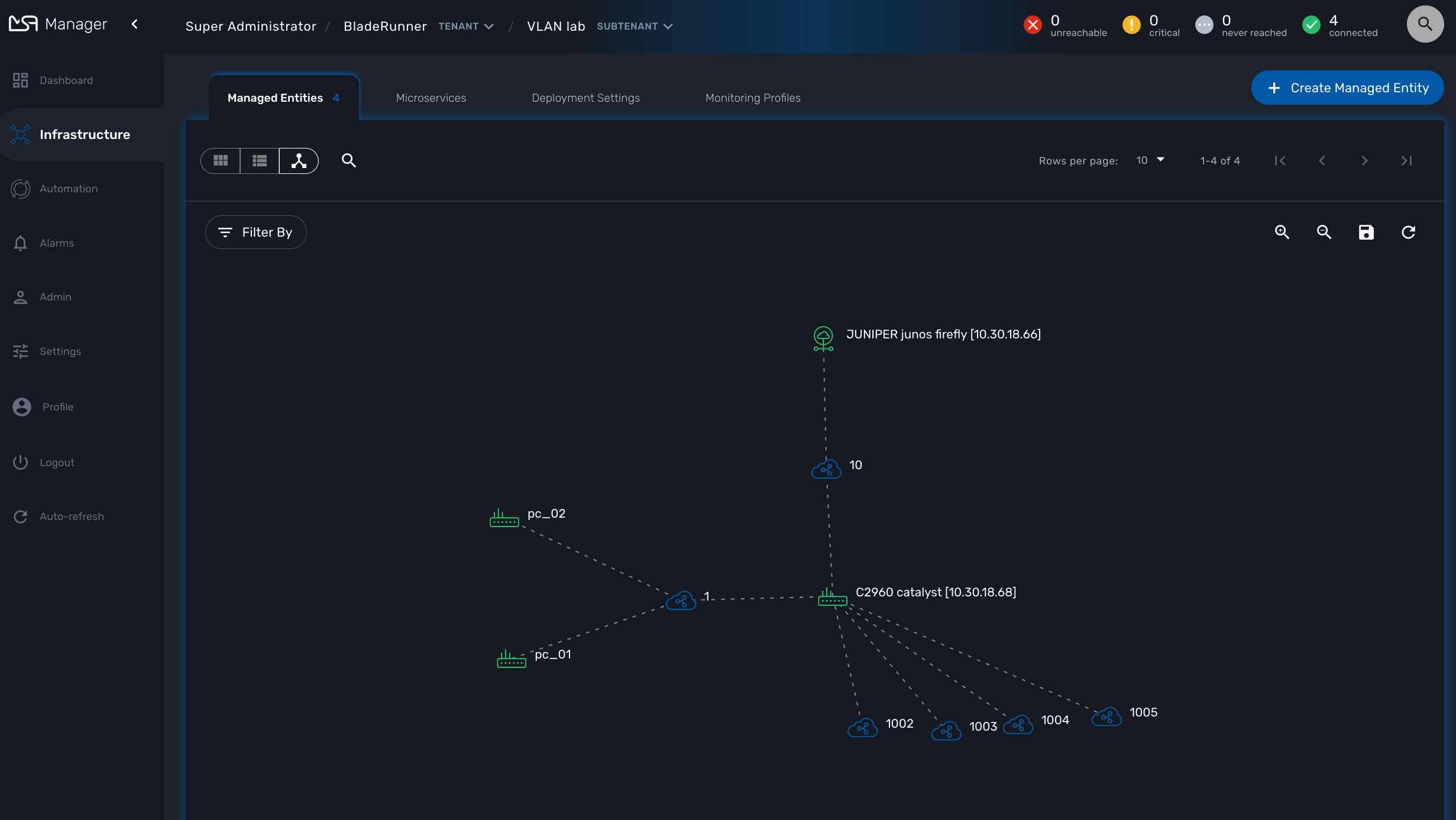
The topology view is available in the "Infrastructure" section of the web user interface, in the tab "Managed Entities".
When you browse to the topology view for the first time, the topology will be calculated automatically based on the L3/SNMP topology mode (see below).
You can refresh the topology view, for instance after your infrastructure has been updated by clicking on the refresh button on the top right corner of the topology canvas.
You can also zoom in and out and re-arrange the layout of the nodes by dragging them with your mouse.
If you want to persist the layout, you can save the topology with the save button on the top right corner of the topology canvas.
Managed Entity categories
On the topology view you can right-click on a managed entity icon and add categories to the managed entity.
This is useful to organize your infrastructure elements.
Use the "Filter By" action to filter your topology view and only display the elements you are interested in.
Workflow and BPM launcher
If you right-click anyway on the topology canvas, a contextual menu will pop-up and from there you have the possibility to trigger the execution of a workflow or a BPM.
This is a useful shortcut when you need to run some automated processes based a visual display of your infrastructure.
Topology types
2 types are available to build and display the topology view:
-
Layer 3 view based on SNMP
-
Layer 2 view based on VLAN
SNMP
The L3 SNMP mode relies on SNMP request to the managed entities to build the topology graph.
Prerequisites
SNMP must be enabled on the managed entities with a read-only community. The community must also be set on the managed entity on the MSactivator™ managed entity form.
How it works
The topology is calculated by a workflow Topology. This workflow is automatically associated with the current subtenant when you browse to the topology screen in the "Infrastructure" section.
When you load or refresh the topology, the workflow will either create a new instance or update the last one that was created. It will loop through each managed entity of the subtenant and execute the CLI command below for each one.
snmpwalk -v2c -c <community> <address> IP-MIB::ipAdEntNetMask
The SNMP mode will rely on the CLI command snmpwalk -v2c -c <community> <address> IP-MIB::ipAdEntNetMask to get the list of IP addresses and network masks from the IP MIB object.
ipAdEntNetMask OBJECT-TYPE
    SYNTAX     IpAddress
    MAX-ACCESS read-only
    STATUS     deprecated
    DESCRIPTION
           "The subnet mask associated with the IPv4 address of this
            entry.  The value of the mask is an IPv4 address with all
            the network bits set to 1 and all the hosts bits set to 0."
    ::= { ipAddrEntry 3 }
For each managed entity, the topology workflow will get the list of IPv4 addresses of this MIB entry and it will build a data structure, stored in the MSactivator™ workflow database, to represent the topology as a graph with links and nodes.
$cmd = "snmpwalk -v2c -c $community $address IP-MIB::ipAdEntNetMask 2>&1";
exec($cmd, $value, $error);                                                             (1)
if (!$error) {
	foreach ($value as $search) {
		if (searchAddress($search, $matches) != false) {
			if ($matches [1] [0] != 127) {
				$address_link = $matches [0] [0];
				$maskAdr = $matches [0] [1];
				$mask = calcMask($maskAdr);
				$address_link_masked = getNetworkByAddressAndMask($address_link, $mask);
				$addressAndMask = $address_link_masked . "/" . $mask;
				createTopologyNetwork(str_replace(".", "_", $addressAndMask), $addressAndMask, "network", "");  (2)
				$context ['Nodes'] [$nodePlace] ["link"] [] ["id"] = $addressAndMask;
			}
		}
	}
} else {
	logTofile($value, "Error : $value \n"));
}| 1 | execute the snmpwalk command to list the IP addresses and masks |
| 2 | create the topology links with the CIDR as the identifier |
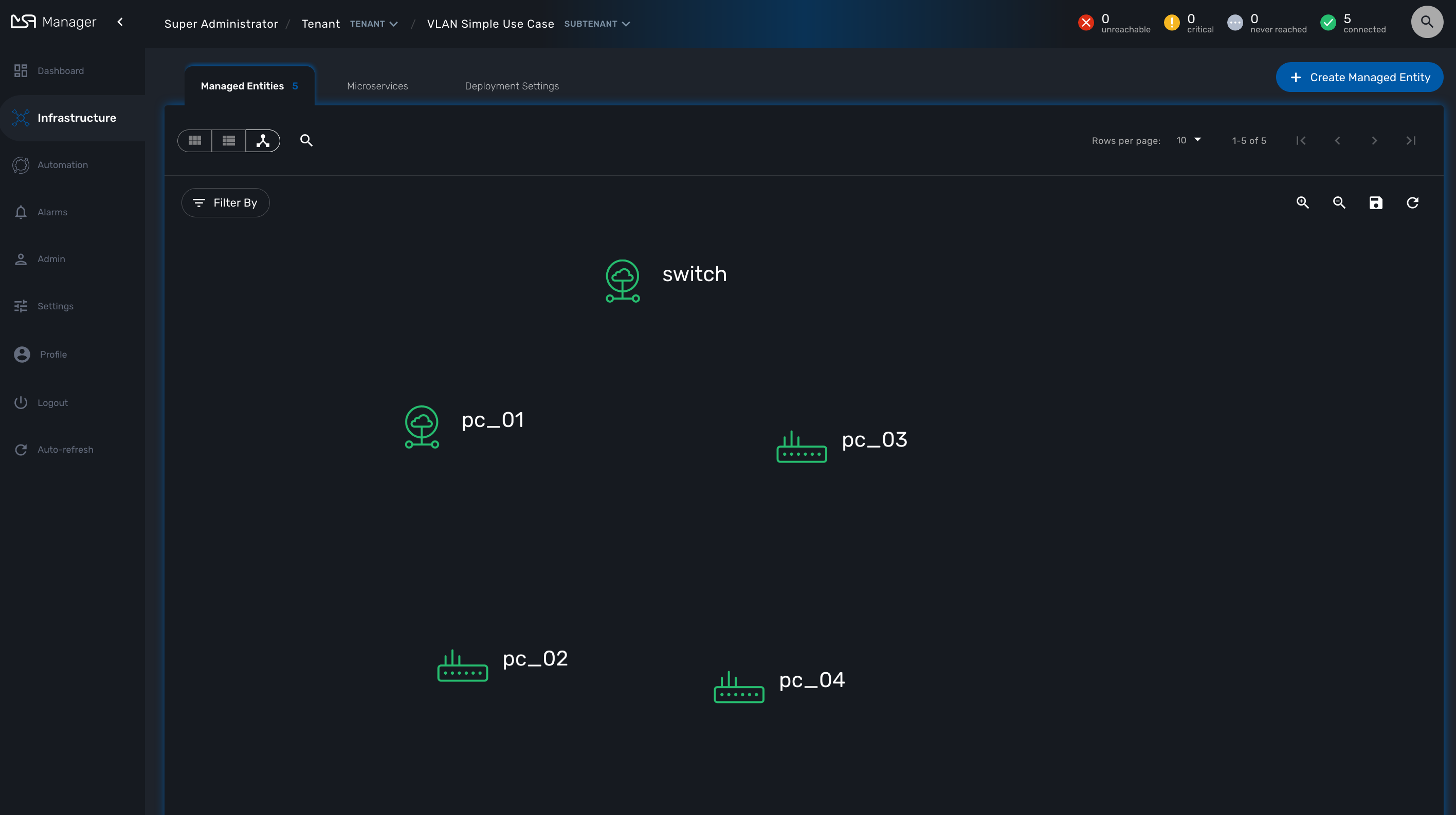
VLAN
The VLAN mode provides a layer 2 view of your infrastructure.
To generate this view you need first to create a new instance of the topology workflow and select "VLAN" for the topology type. Once this is done you will see the layer 2 topology in the topology screen of the infrastructure.
Prerequisites
The VLAN topology relies on microservices to get the vlan of you managed entities for a selected subtenant. It’s therefore mandatory to have a microservice attached to every managed entity you need the vlan information for.
The microservice for vlan should have the following characteristics:
-
be defined in a microservice file named vlan.xml
-
the variable object_id should be set to the vlan ID
Any other variable such as the vlan name can be defined in the microservice for configuration purposes but it will not be used to generate the topology view.
A few examples are available on Github:
How it works
When you load or refresh the topology, the topology workflow will either create a new instance or update the last one that was created. It will loop through each managed entity of the subtenant and import the vlan information based on the microservice implementation of the IMPORT function.
For example, with a linux based switch, the regex
:\svlan_(?<object_id>\w+):\s\S+\s\S+\s\S+\s+\S+\s\S+\s\S+\s(?<state>\w+)
will be applied to the result of the CLI command ip a:
# ip a | grep vlan
4: eth4.200@eth4: <BROADCAST,MULTICAST,UP,LOWER_UP100> mtu 1500 qdisc noqueue master vlan_200 state UP qlen 1000
5: vlan_default: <BROADCAST,MULTICAST,UP,LOWER_UP> mtu 1500 qdisc noqueue state UP qlen 1000
6: vlan_100: <BROADCAST,MULTICAST,UP,LOWER_UP> mtu 1500 qdisc noqueue state UP qlen 1000
7: vlan_200: <BROADCAST,MULTICAST,UP,LOWER_UP> mtu 1500 qdisc noqueue state UP qlen 1000
15: eth4@if16: <BROADCAST,MULTICAST,UP,LOWER_UP100,M-DOWN> mtu 1500 qdisc noqueue master vlan_default state UP
41: eth1@if42: <BROADCAST,MULTICAST,UP,LOWER_UP100,M-DOWN> mtu 1500 qdisc noqueue master vlan_default state UP
43: eth2@if44: <BROADCAST,MULTICAST,UP,LOWER_UP100,M-DOWN> mtu 1500 qdisc noqueue master vlan_default state UP
45: eth3@if46: <BROADCAST,MULTICAST,UP,LOWER_UP100,M-DOWN> mtu 1500 qdisc noqueue master vlan_100 state UP
#
and the result of the import will be 3 vlans, 100, 200 and default.
For non-linux managed entities the process to export the vlan information will be different but a similar result will be stored in the database and used by the workflow to build the data structure to represent the topology.
The code to build the topology node information will resemble to
foreach ($vlans as $vlan) {
	$vlan_id = $vlan->object_id;        (1)
	createTopologyNetwork($vlan_id, $vlan_id, "network", "");       (2)
	$context ['Nodes'] [$nodePlace] ["link"] [] ["id"] = $vlan_id;
}| 1 | get the value of the microservice variable object_id. It’s expected to be the vlan ID. |
| 2 | create the topology link with the vlan ID |
Create you custom topology
You can create your own topology view, either based on an existing one or you can create a completely new one based on the specifics of your infrastructure.
Here are the steps to add a new topology my_topology to your MSactivator™
Step 1: prepare your development environment
The topology workflow is located under /opt/fmc_repository/OpenMSA_WF/ in the container msa_dev, it’s a git repository so you also need to make sure that it is up to date with git status and update your local repository with git pull origin master to get the latest updates.
Under /opt/fmc_repository/Process, there is a symlink to the git repo: Topology → ../OpenMSA_WF/Topology
$ docker-compose exec msa-dev bash
[root@36f98599746a /]# cd /opt/fmc_repository/OpenMSA_WF/
[root@36f98599746a OpenMSA_WF]# git remote -v
origin	https://github.com/openmsa/Workflows.git (fetch)
origin	https://github.com/openmsa/Workflows.git (push)
You can add your own remote to your fork of the openmsa repository or work with the default one. Either way, you need to create a working branch that you will use later to initiate a pull request.
[root@36f98599746a OpenMSA_WF]# git checkout -b my_topology
Switched to a new branch 'my_topology'
Step 2: add a new topology type to the workflow
With the MSactivator™, edit the topology workflow, edit the variable view_type and, in the "Advanced" section add my_topology to the values for the drop-down list.
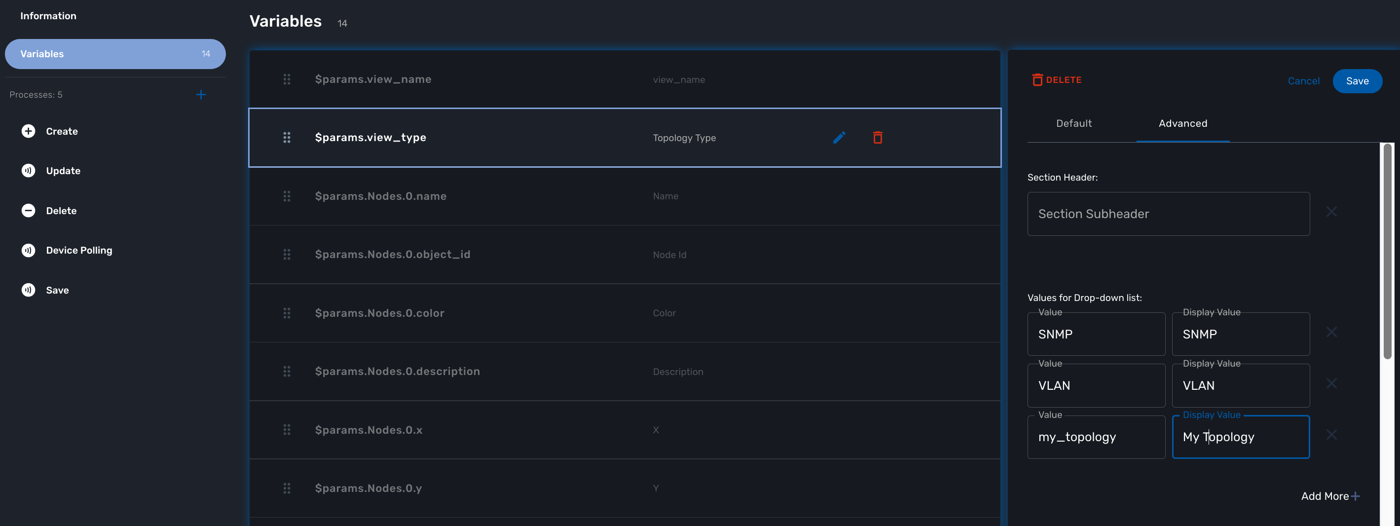
Save the workflow and use git status to see your change
[root@36f98599746a OpenMSA_WF]# git status
On branch my_topology
Changes not staged for commit:
  (use "git add <file>..." to update what will be committed)
  (use "git restore <file>..." to discard changes in working directory)
	modified:   Topology/.meta_Topology.xml
	modified:   Topology/Topology.xml

no changes added to commit (use "git add" and/or "git commit -a")
you can add and commit these files.
[root@36f98599746a OpenMSA_WF]# git lg
* c5f8bf6 - (HEAD -> my_topology) add a new topology view type <Antoine> (5 seconds ago)
Step 3: add a new PHP script to implement the new topology
Go to /opt/fmc_repository/OpenMSA_WF/Topology/Topology_Types
[root@36f98599746a Topology_Types]# pwd
/opt/fmc_repository/OpenMSA_WF/Topology/Topology_Types
[root@36f98599746a Topology_Types]# ll
total 12
-rwxr-xr-x 1 ncuser ncuser 3857 Sep 24 15:13 SNMP.php
-rwxr-xr-x 1 ncuser ncuser  419 Sep 24 15:13 Template.php
-rwxr-xr-x 1 ncuser ncuser 1516 Sep 24 15:13 VLAN.php
You can reuse any of these files to create your own script, we will use Template.php which is an "empty" implementation.
[root@36f98599746a Topology_Types]# cp Template.php my_topology.php
[root@36f98599746a Topology_Types]# chown ncuser.ncuser my_topology.php  (1)
[root@36f98599746a Topology_Types]# ll
total 16
-rwxr-xr-x 1 ncuser ncuser 3857 Sep 24 15:13 SNMP.php
-rwxr-xr-x 1 ncuser ncuser  419 Sep 24 15:13 Template.php
-rwxr-xr-x 1 ncuser ncuser 1516 Sep 24 15:13 VLAN.php
-rwxr-xr-x 1 ncuser ncuser 419 Sep 27 12:55 my_topology.php| 1 | set the file user and group to ncuser |
Add a new commit for this initial file
[root@36f98599746a Topology_Types]# git status
On branch my_topology
Untracked files:
  (use "git add <file>..." to include in what will be committed)
	my_topology.php

nothing added to commit but untracked files present (use "git add" to track)
[root@36f98599746a Topology_Types]# git add my_topology.php
[root@36f98599746a Topology_Types]# git commit -m "new empty implementation"
[my_topology 455ab85] new empty implementation
 1 file changed, 15 insertions(+)
 create mode 100755 Topology/Topology_Types/my_topology.php
Now you are ready to start implementing and testing your new topology.
Step 4: implementation and tests
On the workflow screen, create a new instance with your new topology view. At that point the implementation will be specific to your use case.
Whenever you create a new instance of the process, a dedicated log file is created in the API container, under /opt/jboss/wildfly/standalone/log/process-<INSTANCE_ID>.log.
The workflow instance ID (39 in the screenshot below) is the one displayed at the top left corner of each instance.
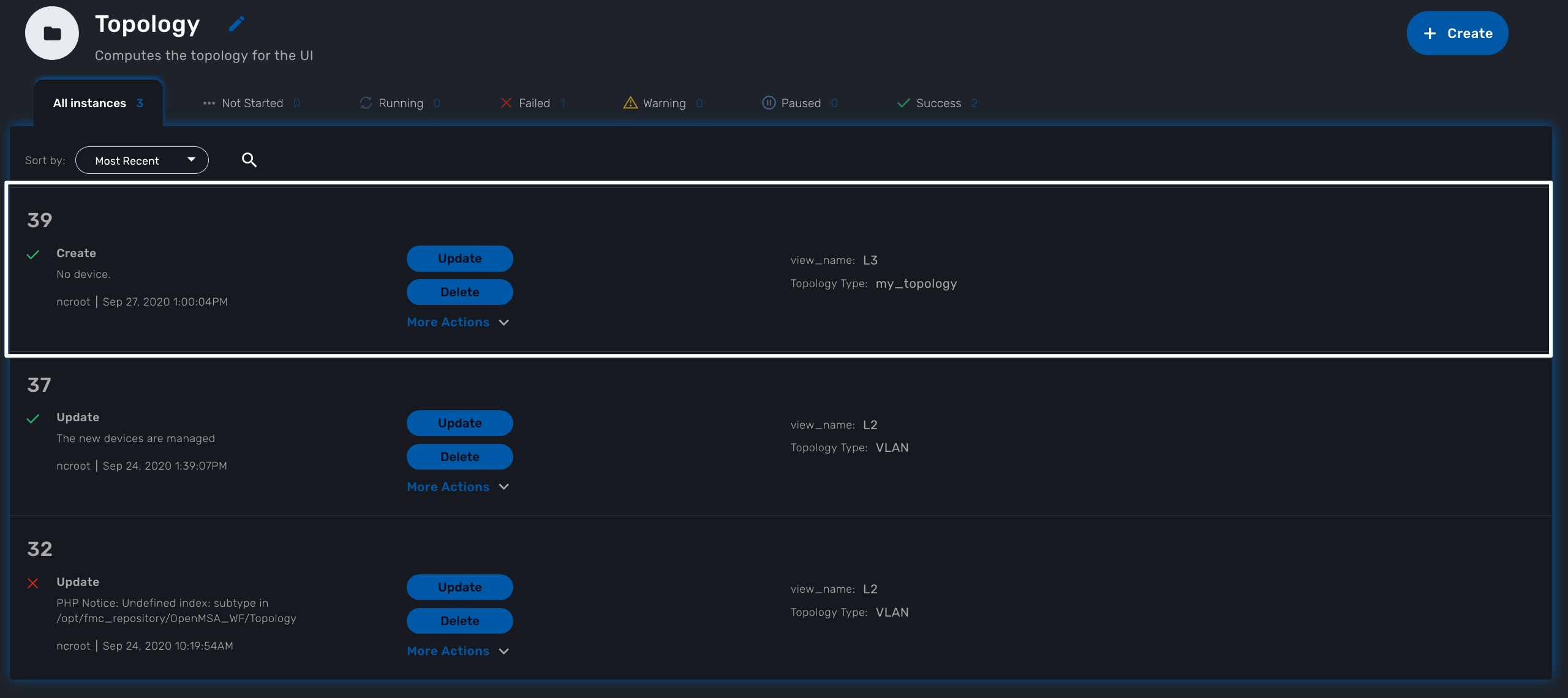
You can monitor the log for debugging purpose: docker-compose exec msa-api tail -F /opt/jboss/wildfly/standalone/log/process-39.log (where 39 is the workflow instance ID
Use the custom functions logToFile and debug_dump to output your debugging information in the log file.
With the code provided in Template.php you will get topology similar to this, without any links.